Bigbot User Manual

General safety instructions

The bigbot is large and powerful and can injure yourself, other people, property, or the robot itself. The following should be read and understood before operation. Keep this product away from children. It is not designed to be used by children. It should be operated by a competent and careful operator. A carefull operator limits the speed near the presence of people or objects.

Before first use

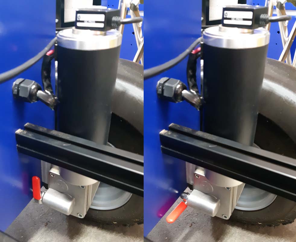
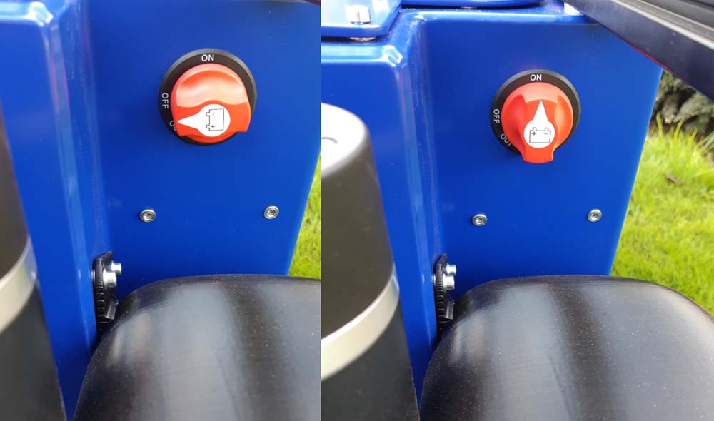
The one or two battery-packs (dependent on the order) are already mounted in the bigbot. Every pack consists of 2 x 12V (or 12.8V LiFePo) batteries connected in series. During transport the lead between the two batteries is removed so it cannot energize the robot unintentionally. You will need to re-connect this lead per battery pack to be able to operate the robot. You need an M5 wrench for this. After connecting the batteries, please charge them completely first.

Mechanically disengage wheels

The wheels can be mechanically disconnected from the motors. This allows you to maneuver the bigbot manually. Maneuvering is not possible if the bigbot is not energized, because than the holding brakes are applied preventing motion.

When the red lever is horizontal the wheel is not engaged, when it is up it is engaged.

On the left wheel engaged (red lever up) and on the right wheel not engaged

Charging the batteries

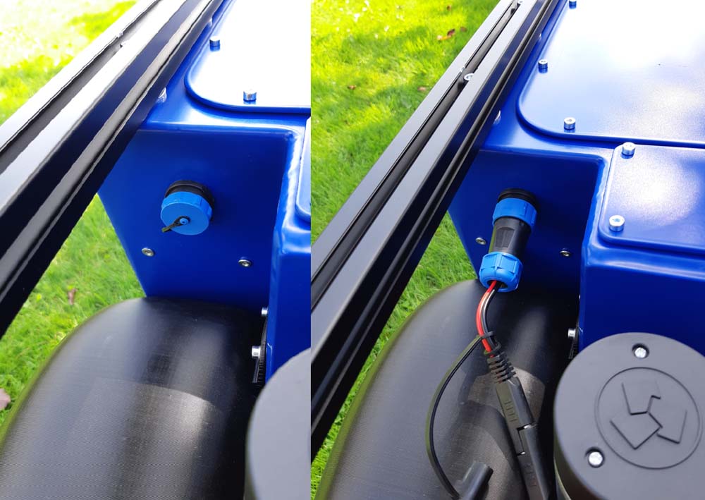
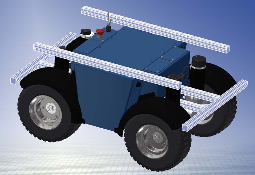
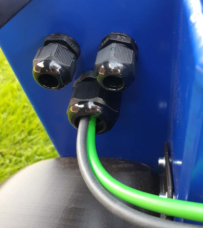
On the rear-left side a 2-pin connector is provided for charging the batteries. The provided charger will fit to this connector in one manner.
On the left the battery plug on the bigbot is closed (to prevent water coming in) and on the right the connector for the battery charger is connected to the bigbot

The batteries are not allowed to be charged in a gas tight container. Thus, it is required to open at least one lid during charging. After connecting the charger with the bigbot you can plug the charger in an 220VAC outlet. The light on the charger will turn red. Once the robot charger lights turn green again, it is completely charged, and you can unplug it from the outlet and the bigbot.

Bigbot Safety Features

The bigbot has a relay which upon activation (normally closed), disconnects the drive, and applies holding brakes (normally closed) on the back motors which will stop the robot abruptly. This relay will be triggered in these two cases:
  1. The manual safety-button, located on the bigbot frame, is pushed;
  2. A safety-switch (SWD) on the remote control is toggled up;
The remote control can only be started if the safety-button is toggled upward (and thus only starts when the drive is disconnected from the main battery voltage).
The manual safety-button on top of the bigbot
The red circle shows the safety-switch (SwD) on the remote control. Toggled down means the drive is powered and the holding brakes are released

Start bigbot

The bigbot comes with a remote control that allows you to drive manually. Before operation make it a habit to disengage the wheels mechanically from the motors. In case of malfunction an energized robot may behave strangely and dangerously.

Turn on the bigbot with the red knob mounted near the right-rear wheel on the frame (to arrow pointing up).

On the left bigbot turned off, on the right bigbot powered
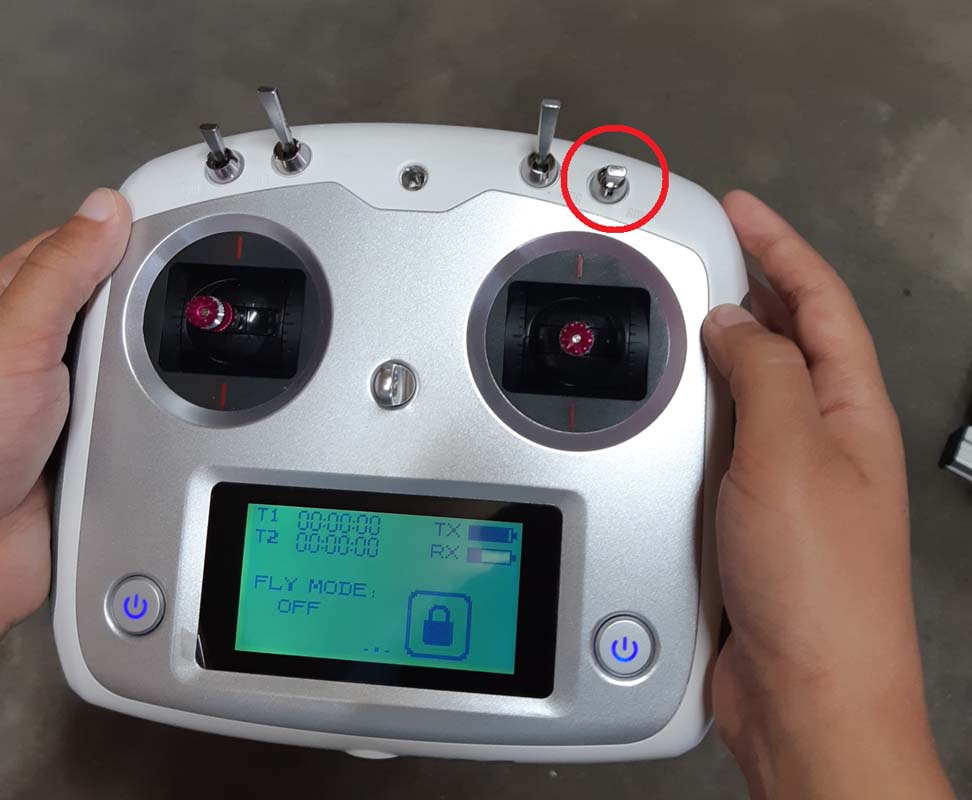
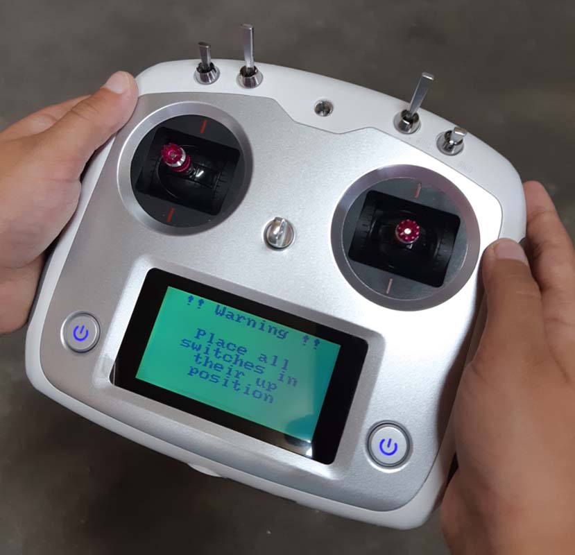
Then turn on the remote by pushing the two on-switches on the front of the remote simultaneously. You should have all switches in the up position otherwise you get a warning (see below).
Warning if you start the rc controller with wrong switch positions
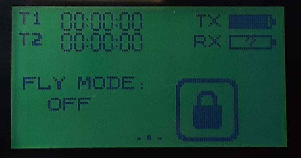
When the switches are all placed up you should be paired with the bigbot automatically (binding is already done in the factory). This should be visible in the remote with a RX bar. If the bigbot not pairs a ?-sign is visible in the RX bar. In this case turn off the bigbot and the remote and check the wiring of the receiver with the roboclaw.
The receiver is not found

Now you toggle the safety-switch (SwD) down on the remote control. You should clearly hear the holding brakes disengage on the rear motors. If you do not hear the holding brakes disengage then the safety-button on the bigbot frame may be engaged. Turn this button left so the button pops up mechanically and disengages.

Now steer the bigbot with the right joystick. You should hear the motors turn (but because you disengaged the wheels it should not move).

If you are confident that everything works you can engage the wheels. If you work near the bigbot make it a habit to toggle the safety-switch on the remote up, thus disabling the drive and engaging the holding brakes.

After engaging the wheels the bigbot will drive as determined by the remote control.
If the motion is not as expected than the mapping of the rc channels may be wrong. The mapping of rc channels for use with an accompanying computer is different than that without this computer.
If you move the right stick forward you should see both channels go to the right on the screen (swipe to right on the screen until you get the axis output).

Eventually, to test the correct wheel rotation direction, eelevate the robot on chocks or boards so that the wheels are not touching the ground.

Bigbot Shutdown

You should turn on off the bigbot with the red knob mounted near the right-rear wheel on the frame (from arrow pointing up to left). If you turn the knop some more to the left you can effectively remove the knob. This may be handy to avoid other people to be able to turn the bigbot on again.

After that, you can shutdown the remote by pushing the two on-switches on the front of the remote simultaneously again. Shutting down the remote while the bigbot is turned on is not possible, this is a safety feature.

You can disengage the wheels from the motors if you want to maneuver the bigbot for storage, or up a trailer.

Maintenance

If you use the AGM batteries than it is best to keep the battery as fully charged, as often as possible. So do recharge between runs.

If the bigbot has not been used in more than one month, charge periodically to ensure the batteries do not drain to low and become damaged.

Do not store the robot for long periods of time on a low charge as the batteries could drop below the recoverable voltage.

Mounting Options

If you use the AGM batteries than it is best to keep the battery as fully charged, as often as possible. So do recharge between runs.

If the bigbot has not been used in more than one month, charge periodically to ensure the batteries do not drain to low and become damaged.

Do not store the robot for long periods of time on a low charge as the batteries could drop below the recoverable voltage.

The bigbot has some 3030 black anodized aluminum profiles which are suitable for mounting brackets, sensors and other components. These profiles are compatible with Bosch, BSP, BSB and B-Type profile systems. The T-slots are 8mm wide.

Two bars are present along the front and back side (600 mm long) which double as a protection for the mudguards. Two bars of 750 mm are present on top of the robot in front-to-back direction.

Aluminium profiles for mounting components are highlighted
A lidar attached to the aluminium profile

As an example, a Sick Lidar is mounted to the 3030 profile with an additional vertical profile (not black). A 3D-printed bracket connects the lidar to the head side of the profile.

The bigbot is fitted with IP68-rated cable glands for cables for different sizes. Some are used as feedthrough for the motors and encoders, but also there are five spare glands which can be used by you.

A plug has been mounted into the spare connectors to avoid water coming in, you need to remove the plug to be able to fit a cable.

Spare glands:

  1. One M25 gland on right front side (for cable diameter 13-18mm)
  2. Two M16 glands on right front side (for cable diameter 5-10mm)
  3. One M12 gland on left front side (for cable diameter 3-6.5mm)
The spare glands n the right front side with two cables mounted (from lidar) in the spare M25 gland.

Environmental limitations

Bigbot has a rating of IP64. The IP rating of the assembled robot is determined by the most vulnerable components which are the motors and externally located encoders which have IP64.

The robot compartments should be closed with all provided bolts (a tightening torque of 0.3Nm is sufficient, do not use a higher torque than 0.5Nm because this may damage the rubber seal). This will ensure a good sealing and preserves the IP64 rating. Operating the robot without properly closing the compartment will lower the IP rating.

Bigbot is designed for reliable operation at normal ambient temperatures (0-40°C). The storage or transport temperature range is -20°C…60°C.

Alterations

Please read the warranty careful. Basically, you are responsible for any modifications you make. Bigbot may not behave as intended and even show dangerous behavior if you alter anything. You will have the full and exclusive responsibility to assure the safety of the resulting altered configuration.

Confirmat Robotics urges you to keep the already implemented safety-features operational at all time (manual safety-button and remote safety-switch). These safety-features do not rely on an accompanying computer and can, and should, be tested before you operate an altered configuration.

Tray for additional equipment

The robot has a tray with internal mounting capabilities for additional equipment. The tray contains a 3mm thick removable PC (poly carbonate) plate. Additional equipment can be bolted on top of it (height 60mm) and under it (140x184x130 mm). The developer can drill the required holes to mount the equipment in the PC plate. If another equipment configuration is required than the PC plate can be exchanged.

The tray with polycarbonate plate and developer areas

Power for your computer and sensors

The batteries nominally operate on 24V (or 25.6V LiPo). However, there is no stabilized 24VDC present. The motor drive is regenerative so when you brake on the motor the drive will recharge the batteries. This elevates the voltage level and probably requires additional measures to protect your equipment. You are responsible for this protection (Please read the warranty carefully).

There is a DC/DC-converter present that delivers a stabilized 12VDC. The converter has short-circuit, overload, undervoltage and input polarity-protection. Additionally, the input is protected by an 30V TVS (Transient Voltage Suppressor) and a fuse. The 12VDC is connected to the motor-drive logic battery input which powers the encoders, drive logic and the rc-receiver (internally roboclaw converts it to 5VDC). Some pins on the roboclaw are not used and may be used to power your sensors at 5VDC. Please consult the roboclaw manual for details.

The current rating of the 12V-converter is 1,25A which allows room to connect additional components to it by the user.

If you want to add a NUC computer typically they require an input voltage of 19V (the non-industrial types). Look at this link for some additional information about using a NUC computer.

Table of Contents