Basic ROS2 configuration
Bigbot is a robotics development platform. Standard use is driving the bigbot with a remote control without any accompanying computer. Now, we integrate a NUC computer in the Bigbot running Ubuntu and ROS2. The computer will receive the remote control steering command (instead of directly the drive) and forward it to the drive. This is a reference design for further ROS-development.
Additional required hardware:
- NUC Computer
- 19V power-supply for the NUC
- USB isolator for drive
- Two USB to TTL-serial (UART) converters
- Optional (recommended) usb-microphone
Prerequisites:
- Fully charge the batteries
- Disengage the wheels mechanically
- Ubuntu and ROS2 galactic are already installed on the NUC
- NUC is configured to startup at power-up (BIOS setting)
- Systemctl and git are installed on the NUC
Add the NUC and power-supply to the tray
The NUC and power supply can be bolted to the tray. In the picture below you see the NUC computer with an USB isolator in the USB port. The 19VDC power supply for the NUC is mounted to the back of the tray so is not visible. Additionally, but not required for the basic ROS configuration is a GPS module, an ethernet switch and a 5V DC-DC-converter to power the ethernet switch.
This tray is bolted to the bigbot with 6 bolts.
The 19VDC power supply is powered from the 24VDC from the DIN-rail on the bottom of the bigbot, behind the TVS (Transient Voltage Suppressor).
Connect wiring between receiver and NUC
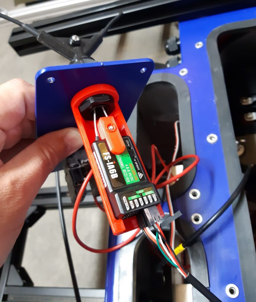
The receiver has three servo-leads connected to it on channel 1, 2 and 5. The leads on channel 1 and 2 are connected to the roboclaw. You can disconnect them, they are not required when we use a computer. Channel 5 should not be disconnected; it is connected to a small relay that is used to drive the larger safety relay.
Now you need a USB to serial converter. The converter has 4 wires. The plus, minus and one signal should be connected to the ibus-location in the receiver (the receiver is not sending any data). This is shown in the picture below. Order from left to right, black (minus), red (plus), white (signal). Green is not connected.
The usb-side of the cable can be connected to the NUC.
Resolving EMC Issues and Power Limitations with IBUS Integration
If you are experiencing EMC (Electromagnetic Compatibility) issues, it is recommended to galvanically isolate the NUC from the IBUS. This helps to minimize interference and ensure stable operation.
Additionally, keep in mind that the IBUS is powered directly from the NUC. In some cases, the current provided may not be sufficient to power devices like relays (e.g., for controlling lights) connected to the IBUS receiver.
For customers who have purchased the Bigbot, a dedicated electronics module is available. This module:
- Galvanically isolates the IBUS from the Bigbot, ensuring interference-free operation.
- Provides a stable 6V power supply for the IBUS, powered by an external power source ranging from 10-24V.
This solution ensures reliable performance, especially in scenarios requiring higher power for IBUS-connected components.
Connect wiring between roboclaw and NUC
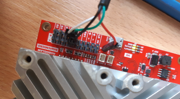
The leads on channel 1 and 2 (receiver) are connected to the roboclaw S1 and S2 pins. Since the leads are removed, also remove them from the roboclaw. Connect the wires as described below. Consult the roboclaw user manual if required.
| Roboclaw location | TTL serial wire |
| S1 I/O | RX (green) |
| S2 I/O | TX (white) |
| GND | GND (black) |
| Do not connect to roboclaw | +5VDC (red) |
Do not connect power (+5) to the roboclaw
Reconfigure the roboclaw
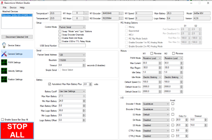
The roboclaw is configured for RC input and now it needs to be changed to UART input. Connect a USB cable between roboclaw and an external computer running Basicmicro MotionStudio and power-on the bigbot.
Start MotionStudio on your external computer and connect to the roboclaw drive. Setup roboclaw control mode to “Packet Serial” iso “RC”. Also set serial address 128 and baudrate 115200.
When done go to the top of the app and press Device > Write Settings which writes the settings to the roboclaw. Now stop MotionStudio and turn off the bigbot.
As a check you can turn on the bigbot and MotionStudio again and read the parameters, the set values for packet serial and baudrate should remain.
Change the program on the remote
To be able to steer the bigbot correctly in RC control the RC sender applies sensor mixing. This sensor mixing is not the appropriate input when driving the bigbot via a computer. You need to disable the sensor mixing on the remote.
Best to do this is to create a new model in SYSTEM > Models and name “Model 2”. You than goto FUNCTION > REVERSE and put every channel on “Nor”.
Than goto FUNCTION > Aux. channels and assign the following buttons:
channel | button |
5 | swD |
6 | Key1 |
7 | SwA |
8 | SwB |
9 | SwC |
10 | VrA |
Than goto FUNCTION > MIX and disable all mixers.
If you want to go back to RC mode (without a computer) go to SYSTEM > Models and choose “Model 1” again, if you want to drive the bigbot with a computer use “Model 2” that you just created.
Please consult the user manual for the Flysky i6S if required.
Clone and build the Bigbot repo
You should be able to connect to the NUC remotely, or add a monitor and keyboard to it, to be able to work on the NUC. At least for installing the required software in the next few steps.
Connect to the NUC and clone the bigbot repo from here locally. They are normal ROS2-packages so you may want to create a separate workspace. Building is done with:
colcon build
Setup udev-rules
We use two USB to serial TTL cables, one is connected to the receiver, and one to the drive. If you plug them into an USB-port a device driver is created called /dev/ttyUSB0 and /device/ttyUSB1. However, it is unclear which device belongs to the receiver or the drive.
The software requires that the device for the receiver is called /dev/ttyRC and for the drive /dev/ttyDRIVE. Some udev-rules can be used to create the correct mapping.
The manner to do this depends on the periphery and the computer that you have. The manner described here works for the components that are used by me but may not work for you. It is described as an example.
Since identical converters are used, which have an identical id, it is not possible to identify them on this id alone. Luckily every USB-port on the NUC has an unique address, so if we use a dedicated USB-ports for the receiver and the drive than we can use this unique address to tell if the drive of receiver is connected.
Before you start you need to add acces to any user to the usb ports. In a terminal type:
sudo usermod -a -G dialout $USER
Now as a super user create the file /usr/lib/udev/rules.d/10-local.rules with the following content:
ACTION==”add”, KERNELS==”1-1″, ATTRS{idVendor}==”067b”, ATTRS{idProduct}==”2303″, SYMLINK+=”ttyRC”
ACTION==”add”, KERNELS==”1-2″, ATTRS{idVendor}==”067b”, ATTRS{idProduct}==”2303″, SYMLINK+=”ttyDRIVE”
KERNELS is the unique usb-address and the idVendor and idProduct are ids of the USB to serial cable. This basically means that any USB to TTL cable (of this type) connected in USB port location 1-1 will be assigned to /dev/ttyRC. Likewise any USB to serial cable connected to 1-2 will be assigned /dev/ttyDRIVE.
To activate the new rules you can type the following in a terminal:
sudo udevadm control –reload-rules && sudo service udev restart && sudo udevadm trigger
If the mapping works as intended than an /dev/ttyRC will appear if you connect the receiver cable, and disappear when you disconnect the cable (and similar for /dev/ttyDRIVE).
Setup systemd-rules for automatically starting the robot software
In the repo the launchfile rcdrive_launch.py is given and can be started in a terminal with:
ros2 launch bigbot_bringup rcdrive_launch.py
With systemctl you can start the launchfile automatically when you boot the NUC . This is done with a systemd unit file. Copy all files under the bigbot repo folder bigbot/systemd to folder $HOME/.config/systemd/user. You must create the folders if they do not exist yet. Since you already installed systemctl you can enable the launch file at startup by enabling the unit file bigbot_rc.service. In a terminal type:
systemctl –user enable bigbot_rc.service
systemctl –user start bigbot_rc.service
If you type the following you should see a status report:
systemctl –user status bigbot_rc.service
Test the bigbot
First read the user manual.
Turn on the bigbot and the rc sender as described in the user manual. It should bind automatically when the remote is powered (via the NUC). if the NUC is started up, which may take a few minutes, the launchfile is running and since that the NUC controls the drive.
If you have added a usb-speaker it will tell you when the bigbot has started up (and will tell you any other useful information) so this is recommened to do.
If you have access to the NUC you should be able to see the joystick topic and the drive topic /cmd.
If you do not see the joystick topic determine if the driver /dev/input/js0 exists. This should be created by the command inputattach (as called in the launchfile) which converts the /dev/ttyRC into a joystick driver. This driver is started with joy_node from package joy.
Now steer the bigbot with the right joystick. You should hear the motors turn (but because you disengaged the wheels it should not move).
If you are convident you can toggle the safety-switch (SwD) down on the remote control. You should clearly hear the holding brakes disengage on the rear motors. You can drive the bigbot around now via the accompanying computer.